
6. Seeing sound
Problem Description & Analysis
Official Problem Statement
“A thin rubber membrane is stretched over a circular frame and driven into vibration by a loudspeaker. A small mirror is attached to the membrane, and a laser beam is reflected off it onto a distant screen. Under certain conditions, the laser spot traces out complex, steady, or evolving geometric patterns. Investigate the relationship between the driving parameters, the membrane’s properties, and the resulting light patterns.”
Vibration Modes of a Circular Membrane
The wave equation for a circular membrane with the boundary condition of zero displacement at the edge ($r = R$) yields Bessel-function solutions. The mode shape for mode $(m,n)$ is:
$$psi_{mn}(r,theta,t) = A_{mn}, J_m!left(frac{k_{mn}, r}{R}right)cos(mtheta),cos(2pi f_{mn}, t)$$
where $J_m$ is the Bessel function of the first kind of order $m$, and $k_{mn}$ is the $n$-th non-zero root of $J_m(k_{mn}) = 0$. The resonance frequency of each mode is:
$$f_{mn} = frac{k_{mn}}{2pi R},c,,qquad c = sqrt{frac{T}{sigma}}$$
where $T$ is the surface tension (force per unit length, N/m), $sigma$ is the surface mass density (kg/m²), and $R$ is the frame radius.
Table of First Bessel Zeros $k_{mn}$
| $m backslash n$ | 1 | 2 | 3 |
|---|---|---|---|
| 0 | 2.405 | 5.520 | 8.654 |
| 1 | 3.832 | 7.016 | 10.173 |
| 2 | 5.136 | 8.417 | 11.620 |
| 3 | 6.380 | 9.761 | 13.015 |
Converting Membrane Vibration to Laser-Spot Motion
A mirror mounted at position $(r_0, theta_0)$ on the membrane tilts as the membrane surface slopes. If the vertical displacement at that point is $z(t)$ and the effective mirror arm length is $ell$, the angular deflection of the laser is:
$$Deltatheta_x(t) approx frac{2}{ell},frac{partial z}{partial x}bigg|_{(r_0,theta_0)},qquad Deltatheta_y(t) approx frac{2}{ell},frac{partial z}{partial y}bigg|_{(r_0,theta_0)}$$
With screen distance $D$, the laser spot coordinates are $(X,Y) = (DDeltatheta_x,, DDeltatheta_y)$.
Lissajous Patterns
When a single mode is driven, both components $Deltatheta_x$ and $Deltatheta_y$ oscillate at the same frequency but with a phase difference $delta$:
$$X(t) = Acos(omega t),qquad Y(t) = Bcos(omega t + delta)$$
For $delta = 0$ or $pi$ the spot traces a straight line; for $delta = pi/2$ an ellipse; for slowly varying $delta$ the ellipse rotates and evolves.
When two modes $(m_1,n_1)$ and $(m_2,n_2)$ are simultaneously excited with frequency ratio $p:q$:
$$X(t) = A_1cos(pomega t + phi_1),qquad Y(t) = A_2cos(qomega t + phi_2)$$
the laser traces a Lissajous figure with ratio $p:q$. Near resonance, the large amplitude and slowly drifting phase difference $phi_1 – phi_2$ produce complex, evolving patterns.
Parameters
T — membrane surface tension (N/m): higher tension raises all frequencies ($f propto sqrt{T}$)
$sigma$ — surface mass density (kg/m²): higher density lowers all frequencies ($f propto 1/sqrt{sigma}$)
$f_{drive}$ — loudspeaker frequency (Hz): selects which mode is excited
$A_{drive}$ — driving amplitude (mm or Pa): sets the pattern size on the screen
$(r_0,theta_0)$ — mirror position on membrane: determines which mode components are visible
D — screen distance (m): sets the overall scale of the pattern
Experimental Setup
To measure resonance frequencies as a function of $R$ and $T$:
- Stretch rubber membranes under controlled tension (using calibrated masses) over circular frames of various radii.
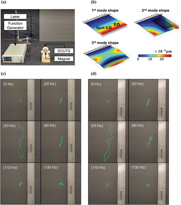
- Sweep the loudspeaker frequency slowly from a few Hz to several hundred Hz; record frequencies that produce stable patterns on the screen.
- Compare the measured ratios $f_{mn}/f_{11}$ to the predicted ratios $k_{mn}/k_{11}$ to verify the Bessel-function model.
- Drive two modes simultaneously by mixing two frequencies near two distinct resonances; compare the observed closed-path pattern with the ratio $k_{m_1n_1}/k_{m_2n_2}$ to verify the Bessel-root frequency prediction.
The wave speed in the membrane can be extracted from $c = 2pi f_{01} R / k_{01}$, and the surface tension from $T = c^2 sigma$.
Animation — Membrane Vibration and Laser Spot Path
Python Analysis
The simulation below shows two outputs:
Left panel: Mode shape $(m,n)$ on membrane — green = up, purple = down, dashed lines = nodal lines.
Right panel: Laser spot trajectory on screen — single mode (ellipse/line) or two modes (Lissajous).
Python Simulation — Bessel Modes and Laser Path
Top row: mode shape on the membrane (green = positive, red = negative, dashed = nodal lines, blue triangle = mirror position). Bottom row: laser-spot trajectory on the screen for each mode.
References
- Kinsler, L. E. et al., Fundamentals of Acoustics, 4th ed., Wiley, 2000 — Chapter on membrane vibration.
- Morse, P. M., Vibration and Sound, McGraw-Hill, 1948 — Full solution of the circular wave equation.
- French, A. P., Vibrations and Waves, MIT Introductory Physics Series, 1971.
- Rossing, T. D., Springer Handbook of Acoustics, Springer, 2007 — Chapter on percussion membranes.
Technical Glossary
| Term | Persian equivalent | Definition |
|---|---|---|
| Chladni patterns | الگوهای کلادنی | Sand figures on a vibrating plate: sand migrates to the nodes of the standing wave |
| Standing wave | موج ایستاده | Interference pattern with fixed nodes (zero amplitude) and antinodes (maximum amplitude) |
| Node | گره | A point of zero amplitude in a standing wave; where sand accumulates in Chladni figures |
| Antinode | شکم | A point of maximum amplitude in a standing wave; located midway between adjacent nodes |
| Resonance frequency | فرکانس تشدید | Frequency at which the plate vibrates with very large amplitude; one per mode shape |
| Eigenmode | مد ویژه | A specific spatial pattern of vibration at a given frequency; each eigenmode produces a distinct Chladni figure |
| Acoustic forcing | تحریک آکوستیکی | Driving the plate's vibration via sound-pressure waves from a loudspeaker |
Suggested Resources
Questions & Discussion
You must be an IYPT member and logged in to view or ask questions.
Log In