
8. Upward-driven disc
Problem Description & Analysis
Official Problem Statement
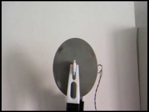
A disc is placed between two spinning wheels that drive it upward. The disc can oscillate about the contact point. Investigate the phenomenon.
Apparatus Geometry
The disc is vertical — like a coin standing on its edge. Two cylindrical rollers grip the flat faces of the disc from either side; the disc rim is not in the groove between the rollers.
• Normal N: horizontal, clamps the disc between the two rollers
• Upward friction f = μN: the roller surface moves upward (via rotation), dragging the disc face upward
• Contact point O: where the roller meets the disc face; if O is above the disc’s center of mass, the disc behaves as a simple pendulum
Core Physics — Mechanical Pendulum
Gyroscopic effects play no dominant role here. The rollers apply upward friction to the disc face — they do not impart significant spin to the disc about its own axis, so the disc’s angular momentum is negligible. The dominant mechanism is a simple pendulum:
Let h be the vertical distance from the contact point O down to the disc’s center of mass CM. When the disc tilts by angle θ, gravity provides a restoring torque — exactly like a pendulum hanging from O:
$$I_O,ddot{theta} = -Mg,h,sintheta$$
Moment of inertia about O (parallel-axis theorem):
$$I_O = underbrace{tfrac{1}{4}MR^2}_{I_{CM}} + M h^2$$
Natural oscillation frequency for small angles:
$$boxed{omega_0 = sqrt{frac{Mgh}{I_O}} = sqrt{frac{gh}{tfrac{1}{4}R^2 + h^2}}}$$
System Parameters
• R — disc radius (m)
• h — vertical distance from contact point O to CM (m) — the key parameter
• I_O = ¼MR² + Mh² — moment of inertia about tilt axis O
• N — normal (clamping) force from each roller (N)
• μ — roller surface friction coefficient
• f = μN — upward friction force from each roller
Vertical (Rising) Motion
The disc rises when the combined upward friction exceeds its weight:
$$2mu N > Mg quadRightarrowquad N > frac{Mg}{2mu}$$
Upward acceleration when this condition holds:
$$a = frac{2mu N – Mg}{M}$$
The vertical (rising) and transverse (tilting) motions are largely decoupled for small oscillations. Their coupling at certain driving speeds produces the chaotic behavior reported in AJP 2025.
Three Behavioral Regimes
| Regime | Condition | Disc Behavior |
|---|---|---|
| Steady rise | θ ≈ 0, perfect symmetry | Disc rises without tilting |
| Pendulum oscillation | h > 0, O above CM | Disc swings about O while rising steadily |
| Unstable | h ≤ 0, O at or below CM | Disc falls (inverted pendulum — no restoring force) |
| Chaotic | Specific driving speeds | No periodic pattern (AJP 2025) |
Numerical Example
$I_O = tfrac{1}{4}(M)(0.06)^2 + M(0.03)^2 = 1.8times10^{-3}M$ kg·m²
$omega_0 = sqrt{9.81 times 0.03 / (1.8times10^{-3})} approx 12.8$ rad/s ≈ 122 RPM
Oscillation period: $T = 2pi/omega_0 approx 0.49$ s
Experimental Setup
Construction
- Rollers: Two cylinders with parallel horizontal axes; rubber or velvet surface for high friction; r_roller = 2–4 cm.
- Drive: Two DC motors with PWM controller, both rotating so that their contact surfaces move upward.
- Disc: Aluminium or steel, vertical; R = 5–10 cm; m = 50–200 g; must be rotationally balanced.
- Adjustable height: The roller contact height relative to disc center (parameter h) must be adjustable — this is the most important experimental variable.
- Safety guard: The disc may be launched sideways — install a transparent guard around the apparatus.
Measurement
- 120fps camera: Track tilt angle θ(t) and oscillation frequency via video analysis.
- IMU (MPU-6050): Gyro + accelerometer mounted at disc center — records θ(t) directly.
- Experimental design: Vary h (roller contact height) and measure oscillation frequency. Compare with pendulum model prediction ω₀ = √(gh / (R²/4 + h²)).
️ Roller axes must be parallel to within 0.5 mm.
️ Both rollers must be at the same height to maintain symmetric contact.
Deeper Analysis — Why Friction Does Not Affect the Oscillation Frequency
A subtle but important point: the upward friction from the rollers has zero effect on the oscillation frequency. The reasoning: we write the torque equation about the contact point O. The friction force f = μN is applied at O, so its moment arm about O is exactly zero:
$$tau_f^{(O)} = vec{r}_{Oto O} times vec{f} = 0$$
Only gravity contributes a restoring torque, with moment arm $hsintheta$. Therefore:
Optimal Contact Height — Maximum Oscillation Frequency
Setting $d(omega_0^2)/dh = 0$:
$$frac{d}{dh}!left[frac{gh}{tfrac{R^2}{4}+h^2}right] = g,frac{tfrac{R^2}{4}-h^2}{left(tfrac{R^2}{4}+h^2right)^2} = 0 quadRightarrowquad boxed{h_text{opt} = frac{R}{2}}$$
At $h = R/2$ the oscillation frequency is maximum:
$$omega_{0,max} = sqrt{frac{g cdot R/2}{tfrac{R^2}{4}+tfrac{R^2}{4}}} = sqrt{frac{g}{R}}$$
• $h to 0$: O approaches CM → zero restoring torque → zero frequency (disc falls without oscillating).
• $h to R$: large moment of inertia → frequency falls again.
Interactive Python Simulation
Three panels generated by numerically solving the disc pendulum ODE:
- Panel 1: $omega_0/omega_text{max}$ vs $h/R$ — bell-shaped curve peaking at $h = R/2$
- Panel 2: $theta(t)$ for five contact heights — clearly different periods
- Panel 3: Phase portrait $(theta, dottheta)$ — closed orbits for stable oscillation
- Table: maximum frequency at h = 0.5R; drops sharply for h = 0.1R or h = R.
- Panel 2: same initial amplitude (18°), clearly different periods — confirms the pendulum model prediction.
- Panel 3: phase ellipses are tightest for h = 0.5R (highest frequency) and widest for extreme h values.
Video Resources
- Upward-driven disk — direct demonstration with motion analysis
References
- Hartl, D.J., & Lutsko, J.F. (2025). The upward-driven disk: a steadily forced chaotic system. American Journal of Physics, 93(8), 620–630.
- Goldstein, H., Poole, C., & Safko, J. (2002). Classical Mechanics, 3rd ed. Addison-Wesley.
- Landau, L.D., & Lifshitz, E.M. (1982). Mechanics, 3rd ed. Pergamon Press.
- IYPT 2027 Problem 8 Official Statement. iypt.org
Technical Glossary
| Term | Persian equivalent | Definition |
|---|---|---|
| Gyroscopic effect | اثر ژیروسکوپی | Tendency of a fast-spinning body to maintain its rotation axis orientation; resists precession |
| Precession | پرسسیون | Slow rotation of the spin axis under a perpendicular torque: $Omega_p = tau / L$ |
| Angular momentum | تکانهی زاویهای | $mathbf{L} = Iboldsymbol{omega}$; conserved when net torque = 0; keeps the disc axis stable |
| Torque | گشتاور | Rotational analogue of force: $boldsymbol{tau} = mathbf{r} times mathbf{F}$; equals the rate of change of angular momentum |
| Rolling contact (point O) | تماس غلشی (نقطهی O) | The contact point with the surface; friction force at O produces zero torque about O → frequency independent of μ |
| Moment of inertia | ممان اینرسی | Resistance to angular acceleration; solid disc about centre: $I = tfrac{1}{2}MR^2$ |
| Optimal height $h$ | ارتفاع بهینه $h$ | Distance from CoM to contact point O; angular frequency is maximised at $h = R/2$ |
Related Images
Suggested Resources
Questions & Discussion
You must be an IYPT member and logged in to view or ask questions.
Log In